PsyLink: First Amplifier Circuit
I had my head stuck in electronics lectures, datasheets, and a breadboard to figure out a decent analog circuit for amplifying the signal. It sounds so straight forward, just plug the wires into the + and - pin of an operational amplifier, add a few resistors to specify the gain of the OpAmp, and feed the output to the analog input pin of the Arduino... But reality is messy, and it didn't quite work out like that.
Here's a list of problems:
- The voltage I measured from the electrodes seemed incredibly fragile. As soon
as I wanted to do something with it, it seemed to change. This could be due
to the high impedance of the skin, causing a drop in voltage as soon as one
draws any current.
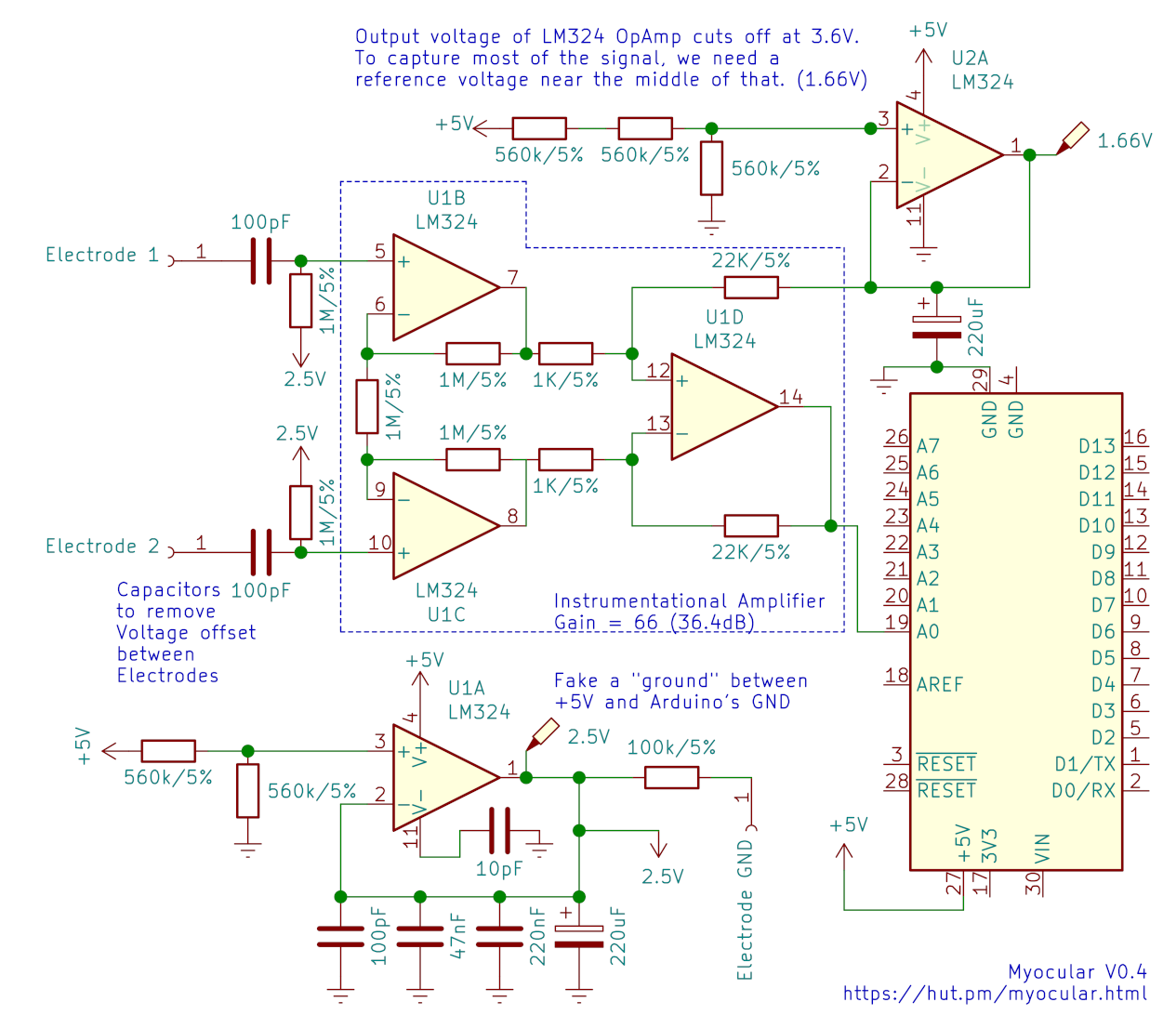
- Solution: Used buffer amplifiers, in an instrumentation amplifier arrangement. Patrick Mercier from UCSD has a great lecture on that
- One electrode may have a DC voltage offset compared of the other electrode.
When this gets large (~50mV+), the amplified voltage difference gets off the
scale.
- Solution: Added capacitors that filter out the DC component. Through experimentation I found that 100pF worked best. Curiously, this is the same capacitance that's sometimes used to model the skin
- The OpAmp amplifies not just the signal but also the noise, like:
- Power line hum from USB connection
- Electromagnetic Interference
- Fluctuations in resistance/capacitance between electrode and muscle
- Solutions:
- Disconnect Laptop from main grid
- Keep wires short
- Add decoupling capacitors
- Perform occult protection magic ceremony
- In the future, perhaps some shielding or bandpass filtering
- I ordered a part that requires min. +/-2.25V. The Arduino supplies 3.3V, so
all is well, right? Nope. It means that I need negative 2.25V as well as
positive 2.25V.
- Solution: Increased the voltage of the entire circuit to 5V, which the Arduino conveniently supports by changing a solder jumper. The middle-ground reference voltage rose from 1.65V to 2.5V, leaving enough room for the required +/-2.25V. I don't actually use the part yet, but I wanted to prepare for it.
- The 2.5V reference voltage from the voltage divider
strongly fluctuated, messing up the output from the OpAmp.
- Solutions:
- Buffer amplifier after the voltage divider
- Bypass capacitors close to the OpAmps
- Solutions:
- The LM324N OpAmp that I used has an output voltage limit of 3.6V (at a supply
voltage of 5V.) That cuts off a good chunk of the signal.
- Solution: I added a second reference voltage at 1.66V so the output centers around that. (Conveniently, the output limit of 3.6V is close to the Arduino's ADC reference voltage of 3.3V.)
- Should I even do any of this? I'm limiting the neural network by introducing
my bias about what a clean signal looks like. Any circuit will invariably
filter out certain information, enhance other information, and add irrelevant
noise. How do I know that the information that I filter out (e.g. the DC
offset voltage between electrodes, or even what I consider irrelevant noise)
isn't useful to the neural network?
- Solution: Keep the signal processing reasonably minimal
I also connected the electrode signal to ground with a 1MΩ resistor which greatly improved the signal, and I have no idea why.
One peculiar thing I noticed was that the signal seemed stronger when my laptop was connected to the power supply. It superimposed noise, but also seemed to increase differences in electrode voltages. I don't quite understand this yet, but 2 things follow from that:
- For replication purposes, I'm using a Lenovo Thinkpad T460p switched to the Intel GPU, which creates it's own particular noise patterns, even when unplugged from the grid.
- I should try out modulating the ground electrode voltage with a controlled low frequency pattern to see if this improves signal to noise ratio. Ideally <30Hz or >500Hz so I can easily filer it out later.
Some of the references I used:
- Olimex "SHIELD-EKG-EMG"
- EEVblog OpAmps Tutorial
- EEVblog Bypass Capacitor Tutorial
- Patrick Mercier's lectures on Instrumentational Amplifiers
- BioPhysical Modeling, Characterization and Optimization of Electro-Quasistatic Human Body Communication, arXiv:1805.05200v1
The resulting circuit: [KiCad Eeschema file]
And the signals look like:


Yellow and green are two electrodes, right after their respective OpAmp, and purple is (yellow-green)*20.
This should be good enough to move forward, but I bought some INA128 instrumentation amplifiers and perhaps I will tinker some more to get an even better signal. Can't wait for the next prototype though :).
In other news, I watched Dr. Gregory House explain forearm muscles, so next time my electrode placement will be better than random!
And since I learned KiCad for creating the above schematic, I thought I'd add schematics for the previous models as well, see Source Code section.
— 2021-04-24, by hut, tags: #psylink