PsyLink: PCB Time
Today I made a new version of the PCB that processes the signals from one electrode pair:
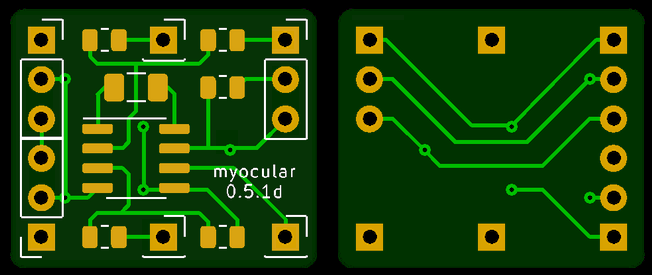
Actually, several versions. This is the 4th iteration, and let's not even look at the previous ones because they were just plain wrong. I stared at this design for a long time though and couldn't find another problem, so I went ahead and ordered 30 pieces of it. Can't wait to find out in what way I messed up :'D And hey, maybe it'll actally work.
Main features:
- Dimensions: 20x17x1.6mm, rounded corners
    - Tiny enough to fit between 2 electrodes!
- 2 connectors for electrodes, at the middle top & bottom
- 1 connector for the output at the bottom right corner (on the front side. The back
  side is mirrored)
- 3 power line connector ports on the other corners, with 3 pins each:
    1. The signal reference voltage
    2. Ground
    3. +6V from the battery
- 3 capacitors, 3 resistors, 1 integrated circuit
To avoid having a kilogram of cables on the device, this board supports wiring in a mesh network topology, where the boards share the power lines amongst each other using the redundant power line connector ports. One board can power two other boards, which in turn can power 4, and so on.
The bypass capacitor between ground and V+ will hopefully keep the voltage stable, though I'm a bit worried about the reference signal. If necessary, I can "abuse" the reference signal pin of the power line connector ports to add extra ground electrodes. I considered adding an extra opamp on every board to generate a fresh reference voltage but that would make the circuit too big for my taste.
— 2021-04-30, by hut, tags: #psylink